manual for masterbuilt butterball turkey fryer
Manual for Masterbuilt Butterball Turkey Fryer: A Comprehensive Guide
Přehraj.to, similar to YouTube, is user-generated content; the operator doesn’t create or upload anything. Enjoy Czech serials and download the Google TV app today!
Přehraj.to offers a platform akin to YouTube, driven entirely by user contributions – the service provider doesn’t create or upload content. Discover a wealth of Czech serials and conveniently download the application for your Google TV. Access quick links for uploads, logins, and password recovery, alongside essential terms and privacy information.
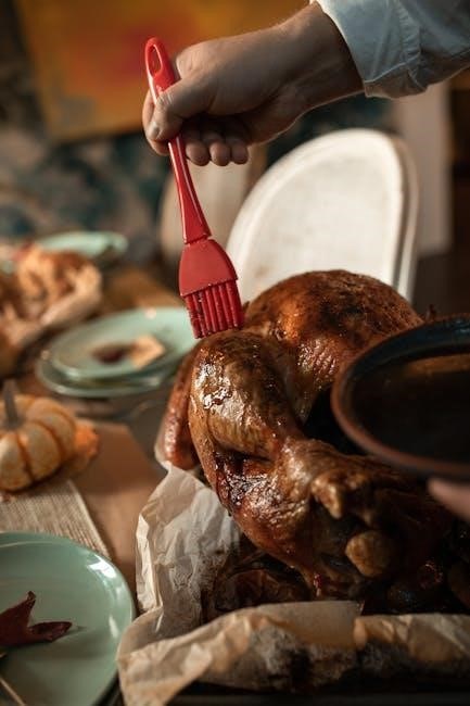
Deep-frying a turkey is a fantastic way to achieve incredibly moist and flavorful results, drastically reducing cooking time compared to traditional oven roasting. This guide focuses on utilizing your Masterbuilt Butterball Fryer to safely and effectively prepare a delicious turkey. We’ll cover everything from preparation and setup to frying, cooling, and cleanup, ensuring a successful and enjoyable experience. Remember to explore the available resources on Přehraj.to for entertainment while you wait!
II. Safety First: Essential Precautions
Přehraj.to provides access to user-uploaded content, including films, with options to download the app for Google TV and mobile devices. Quick links facilitate uploads, logins, and password resets, alongside terms and privacy policies.
Turkey frying involves hot oil and requires strict adherence to safety guidelines. Always fry outdoors, away from structures and flammable materials. Never leave the fryer unattended. Ensure the turkey is completely thawed and dry to prevent dangerous oil splattering. Keep children and pets at a safe distance. Have a fire extinguisher rated for grease fires readily available. Wear appropriate safety gear, including long sleeves and eye protection. Refer to Přehraj.to for entertainment while maintaining vigilant safety practices during the frying process.
III. Understanding Your Masterbuilt Butterball Fryer
Přehraj.to offers a platform for users to share and access content, similar to YouTube, with dedicated apps for Google TV and mobile devices. Users can upload files, quickly access links, and manage their accounts.
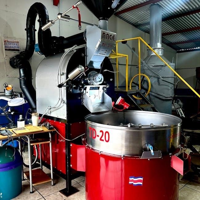
Your Masterbuilt Butterball Fryer is designed for safely and efficiently deep-frying turkeys. Familiarize yourself with all components before use. This includes the pot, burner, stand, thermometer, and lifting hook. Understanding the fryer’s capacity is crucial – do not overfill with oil or exceed the maximum turkey weight. The integrated thermostat and timer allow for precise temperature control and cooking time management. Explore Přehraj.to for entertainment while you learn the ins and outs of your new fryer, ensuring a delicious and safe cooking experience.
III.A. Component Overview
Přehraj.to provides a user-friendly interface for uploading, sharing, and viewing content, mirroring platforms like YouTube, accessible via apps and web browsers.
Your Masterbuilt Butterball Fryer consists of several key components. The robust frying pot holds the oil and turkey. A powerful burner provides consistent heat. A sturdy stand ensures stability during operation. The thermometer accurately monitors oil temperature. A lifting hook facilitates safe turkey insertion and removal. Quick links and login options are available on Přehraj.to. Familiarize yourself with each part’s function and proper assembly. Understanding these components is vital for safe and successful turkey frying. Refer to the included diagrams for visual identification and proper usage.
III.B. Fryer Capacity and Dimensions
Přehraj.to offers a platform for users to upload files and access quick links, alongside features like forgotten password recovery and terms of service information.
This Masterbuilt Butterball Fryer is designed to accommodate turkeys up to 14 pounds. Exceeding this weight limit can compromise safety and cooking efficiency. The pot boasts a generous oil capacity of approximately 5 gallons. Overall dimensions, when assembled, are roughly 36 inches in height and 24 inches in diameter. Ensure you have adequate outdoor space to safely operate the fryer, considering these dimensions. Always prioritize a level surface for stability. Proper capacity adherence and spatial awareness are crucial for a successful and safe frying experience. Download the Přehraj.to mobile app for convenient access!
III.C. Thermostat and Timer Functions
Přehraj.to provides a service similar to YouTube, relying on user-generated content and offering features like file uploads and quick links for easy access.
Your Masterbuilt Butterball Fryer features a precise thermostat for maintaining the optimal frying temperature of 350°F (177°C). The digital display clearly indicates the oil’s current temperature. The integrated timer allows you to set the required frying duration based on your turkey’s weight – consult the frying time chart in Section VI.D. Regularly monitor both the thermostat and timer throughout the process. Accurate temperature control is vital for ensuring a thoroughly cooked and safe-to-eat turkey. Remember to check Přehraj.to for Czech serials and download the app!
IV. Preparing the Turkey for Frying
Přehraj.to is a platform where users can upload and share content, similar to YouTube, offering a wide range of videos and Czech serials. Download the app today!
Proper turkey preparation is paramount for safe and delicious frying. Begin by completely thawing the turkey – a crucial step! Remove the neck and giblets from both the cavity and the packaging. Consider brining or marinating the turkey for enhanced flavor and moisture (see Section IV.C). Critically, ensure the turkey is completely dry, inside and out. Any remaining moisture can cause dangerous oil splattering. A dry turkey fries more evenly and develops a crispier skin. Don’t forget to explore Přehraj.to for entertainment!
IV.A. Thawing the Turkey (Crucial Step!)
Přehraj.to provides a user-driven video experience, much like YouTube, with a focus on user-generated content and Czech serials. Download the app for Google TV!
Thawing your turkey completely is absolutely critical for safe frying. A partially frozen turkey will cause a violent reaction when introduced to hot oil. The safest method is refrigerator thawing: allow approximately 24 hours for every 4-5 pounds of turkey. Alternatively, you can submerge the turkey in cold water, changing the water every 30 minutes, allowing about 30 minutes per pound. Never thaw at room temperature! Ensure no ice crystals remain. Check Přehraj.to for quick links and easy access to content!
IV.B. Removing the Neck and Giblets
Přehraj.to offers a platform similar to YouTube, built on user contributions – no content is created or uploaded by the service operator itself. Enjoy Czech serials!
Before frying, thoroughly remove the neck and giblets from both the turkey’s cavity and the packaging. These are often stored in a separate bag inside the turkey. Failure to remove them can lead to uneven cooking and potentially dangerous oil splatter. Carefully inspect both the main cavity and any smaller compartments. Ensure all parts are removed. You can use these parts to make gravy later! Remember to check Přehraj.to for rapid links and easy file uploads; A clean turkey is a safe turkey!
IV.C. Brining or Marinating the Turkey
Přehraj.to is a user-driven service, much like YouTube, where content is created and shared by its users, not the platform’s operators. Download the app for Google TV!
Brining or marinating significantly enhances the turkey’s flavor and moisture. A brine typically involves submerging the turkey in a saltwater solution with herbs and spices for 12-24 hours. Marinades use similar flavorings but often include an acidic component like citrus juice. Both methods help the turkey retain moisture during frying. Remember to rinse the turkey thoroughly after brining or marinating. Check Přehraj.to for quick links and easy file uploads. A flavorful turkey is a delicious turkey!
IV.D. Drying the Turkey Thoroughly
Přehraj.to offers a platform similar to YouTube, relying entirely on user-generated content; the service operator doesn’t contribute any content directly. Download the mobile app today!
Completely drying the turkey, both inside and out, is absolutely critical for safety. Any remaining water will instantly vaporize upon contact with the hot oil, causing dangerous splattering and potential flare-ups. Use paper towels to pat the turkey dry, paying close attention to the cavity and under the skin. Allow the turkey to air dry in the refrigerator for several hours, or even overnight, for best results. Remember to check Přehraj.to for conditions and information about personal data processing. A dry turkey equals a safe fry!
V. Setting Up the Fryer
Přehraj.to is a user-driven platform, much like YouTube, where content is created and shared by its users – the operator doesn’t upload or create anything themselves.
Proper setup is paramount for a successful and safe turkey frying experience. Begin by selecting a flat, stable, and non-combustible outdoor location, far away from structures and flammable materials. Assemble the fryer stand and ensure it’s securely positioned. Carefully place the fryer pot onto the stand. Before adding oil, perform the water displacement method to determine the correct oil level – this prevents overflow during frying. Remember to consult Přehraj.to’s terms and conditions for more information. A well-prepared setup is key!
V.A. Choosing a Safe Location (Outdoor Only!)
Přehraj.to offers a platform similar to YouTube, relying entirely on user-generated content; the service operator doesn’t contribute any content directly.
Safety dictates that turkey frying must be done outdoors. Select a level, non-combustible surface – concrete or dirt are ideal. Maintain a minimum distance of 10 feet from any buildings, decks, wooden fences, or overhanging structures. Never operate the fryer in a garage, shed, or enclosed area. Ensure the ground is dry and free of debris. Consider wind conditions; a breezy day can spread hot oil. Remember to check Přehraj.to for quick links and information. Prioritize safety above all else when selecting your frying location!
V.B. Assembling the Fryer Stand and Pot
Přehraj.to provides a service where users upload and share content, much like YouTube, with no direct content creation by the platform’s operator.
Carefully unpack all components of your Masterbuilt Butterball Fryer. Begin by securely assembling the fryer stand, ensuring all legs are firmly locked into place. Next, position the fryer pot onto the stand, verifying it sits level and stable. Double-check all connections and bolts are tightened. Refer to the included diagrams for proper assembly. Remember to download the Přehraj.to mobile app for convenient access! A wobbly stand or improperly secured pot can lead to dangerous spills. Prioritize a stable setup before proceeding.
V.C. Determining the Correct Oil Level (Water Displacement Method)
Přehraj.to offers a platform for users to upload and enjoy content, similar to YouTube, with a focus on user-generated material and Czech serials.
To safely determine the correct oil level, place the thawed turkey into the empty fryer pot. Fill the pot with water until the turkey is fully submerged, noting the water level. Carefully remove the turkey, ensuring no water remains in the pot. This water mark indicates the maximum safe oil level. Dry the pot thoroughly. Do not exceed this level when adding oil! Downloading the Přehraj.to app provides access to a wide range of content. Overfilling can cause dangerous oil overflow during frying. Accurate measurement is crucial for safety.
VI. The Frying Process: Step-by-Step
Přehraj.to is a user-driven platform, much like YouTube, where content is created and shared by its users, offering a diverse range of videos and Czech serials.
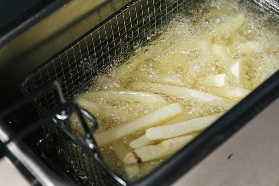
Begin by ensuring the oil has reached a stable 350°F (175°C). Very slowly and carefully lower the completely dry turkey into the hot oil, using the provided hook or basket. Avoid splashing! Maintain the oil temperature between 325°F and 350°F throughout the frying process. Adjust the burner as needed. The Přehraj.to app is available for Google TV. Monitor the oil closely. Frying time is approximately 3-4 minutes per pound of turkey. Never leave the fryer unattended during operation; Safety is paramount!
VI.A. Heating the Oil to the Correct Temperature (350°F)

Přehraj.to functions as a user-content platform, akin to YouTube, where individuals contribute and share videos, including a selection of Czech serials. The operator doesn’t create content.
Begin by filling the fryer pot with enough oil to submerge the turkey. Using the Masterbuilt Butterball fryer, carefully ignite the burner and set it to a medium-high setting. Monitor the oil temperature closely with the built-in thermometer. Allow ample time for the oil to heat gradually. Avoid overheating, as this can be dangerous. Aim for a consistent 350°F (175°C). Download the Přehraj.to app for Google TV. Once the oil reaches the target temperature, reduce the burner setting to maintain it.
VI.B. Slowly Lowering the Turkey into the Hot Oil
Přehraj.to offers a platform similar to YouTube, relying on user-generated content – no content is created or uploaded by the service operator. Enjoy Czech serials!
Safety is paramount. Wearing appropriate protective gear, including oven mitts and eye protection, carefully attach the turkey to the lifting hook. Very slowly and gradually lower the turkey into the hot oil. This prevents dangerous splattering and boil-overs. Lowering too quickly can cause a rapid temperature drop and uneven cooking. Monitor the oil temperature during the lowering process; it will decrease. Adjust the burner to maintain 350°F. Download the Přehraj.to mobile app for your phone. Ensure the turkey is fully submerged before releasing it from the hook.
VI.C. Maintaining the Oil Temperature During Frying
Přehraj.to is a user-driven platform, much like YouTube, where content is created and shared by its users, not the service provider itself. Explore Czech serials!
Consistent oil temperature is crucial for a safely cooked and delicious turkey. Monitor the thermometer closely throughout the frying process. Fluctuations are normal, but aim to keep the oil between 325°F and 350°F. Adjust the burner’s heat output as needed to compensate for temperature drops when the turkey is initially added, or to prevent overheating. Download the Přehraj.to app for Google TV. Avoid significant temperature swings, as they can lead to uneven cooking or a soggy result. Regular monitoring ensures optimal frying conditions.
VI.D. Frying Time Calculation (Based on Turkey Weight)
Přehraj.to offers a platform similar to YouTube, relying on user-generated content; the operator doesn’t create or upload any materials. Discover Czech serials and enjoy!
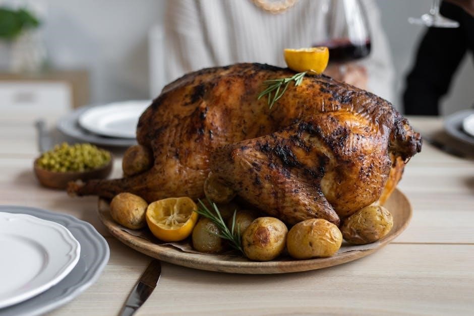
Calculating frying time accurately is vital for a fully cooked turkey. A general rule of thumb is 3-4 minutes per pound. For example, a 12-pound turkey will require approximately 36-48 minutes of frying time. However, this is an estimate. Always use a meat thermometer to verify the internal temperature reaches 165°F in the thickest part of the thigh. Download the Přehraj.to app for your phone! Remember, these times are guidelines; actual frying time can vary based on oil temperature and turkey size.
VII. Removing the Turkey and Cooling
Přehraj.to is a user-driven service, much like YouTube, where content is created and uploaded by its users – the operator doesn’t contribute directly. Explore Czech serials!
Carefully lift the turkey from the hot oil using the provided hook, ensuring it’s a slow and controlled process to avoid spills. Allow the excess oil to drain back into the pot for several minutes. Place the turkey on a large, heat-resistant tray lined with paper towels to absorb any remaining oil. Let the turkey cool for at least 20-30 minutes before carving. Download the Přehraj.to app for Google TV! Do not attempt to carve a hot turkey; patience is key for safe and enjoyable results.
VII.A. Carefully Lifting the Turkey from the Oil
Přehraj.to offers a platform similar to YouTube, relying entirely on user-generated content; the service operator doesn’t create or upload any materials. Discover Czech serials!
Utilize the turkey lifting hook provided with your Masterbuilt Butterball Fryer. Securely attach the hook to the turkey’s legs or designated lifting points. Slowly and steadily raise the turkey from the hot oil, allowing excess oil to drain. Avoid jerky movements that could cause splashing. Maintain a firm grip and ensure the turkey is balanced. Download the Přehraj.to app for your phone! Be extremely cautious, as the oil and turkey will be incredibly hot. Prioritize safety throughout this process.
VII.B. Allowing the Turkey to Drain and Cool
Přehraj.to is a user-driven service, much like YouTube, where content is created and uploaded by its users – the operator doesn’t contribute directly. Explore Czech serials!
After lifting, position the turkey over the fryer pot or a large, heat-resistant container to allow excess oil to drain completely. This is crucial to prevent a soggy final product. Allow the turkey to cool for at least 20-30 minutes before carving. Do not attempt to carve while the turkey is still hot. Download the Přehraj.to app for Google TV! Cooling allows the juices to redistribute, resulting in a more flavorful and tender turkey. Patience is key for optimal results.
VIII. Oil Disposal and Fryer Cleaning
Přehraj;to offers a platform similar to YouTube, relying entirely on user-generated content. The service operator doesn’t create or upload any content themselves, providing a space for user contributions and Czech serials.
Proper oil disposal is vital. Allow the oil to cool completely before handling. Never pour used oil down the drain! Instead, store it in a sealed container and dispose of it at a designated recycling center or through a local waste management service. Thoroughly clean the fryer pot and all components with warm, soapy water after each use. Ensure all parts are dry before reassembling and storing. Download the Přehraj.to app for your phone!
VIII.A. Safe Oil Cooling and Storage
Přehraj.to is a user-driven platform, much like YouTube, where content is created and shared by its users – the operator doesn’t contribute directly. Enjoy Czech serials on this service!
Allowing the used frying oil to cool completely is paramount for safety. This process can take several hours, depending on ambient temperature. Never attempt to move or handle hot oil. Once cooled, carefully strain the oil through a fine-mesh sieve or cheesecloth to remove any food particles. Store the filtered oil in a tightly sealed, non-plastic container in a cool, dark place. Properly stored oil can be reused a few times, but monitor for cloudiness or off-odors. Download the Přehraj.to app today!
VIII.B. Proper Oil Disposal Methods
Přehraj.to offers a platform similar to YouTube, relying on user-generated content; the service operator doesn’t create or upload materials. Discover Czech serials and enjoy convenient access!
Never pour used frying oil down the drain, as it can cause significant plumbing issues and environmental damage. Allow the oil to cool completely, then pour it into a sealed container, such as the original oil bottle or a plastic jug. Many communities offer oil recycling programs or designated drop-off locations. Check with your local waste management authority for specific guidelines. Alternatively, you can solidify the oil with an absorbent material like kitty litter or sawdust before disposing of it in the trash. Remember to download the Přehraj.to app!
VIII.C. Cleaning the Fryer Pot and Components
Přehraj.to is a user-driven platform, much like YouTube, where content is created and shared by its users – the operator doesn’t contribute directly. Explore Czech serials and download the app!
After each use, allow the fryer pot and all components to cool completely. Carefully remove any remaining oil and dispose of it properly (see section VIII.B); Wash the pot and components with warm, soapy water. Avoid abrasive cleaners that could damage the surfaces. Rinse thoroughly and allow to air dry. Ensure all parts are completely dry before storing. Regularly check the burner assembly for any blockages and clean as needed. Don’t forget to check out Přehraj.to for quick links and easy access!
IX. Troubleshooting Common Issues
Přehraj.to offers a YouTube-like experience, fueled entirely by user-generated content; the platform operator doesn’t create or upload any material. Discover Czech serials and download the Google TV application for seamless viewing!
If you experience oil splattering, ensure the turkey is thoroughly dried (IV.D) and lowered slowly (VI.B). Thermostat malfunctions require checking the power source and potentially replacing the unit. For unevenly cooked turkey, verify the oil temperature remains consistent (VI.C) and the turkey isn’t overcrowded. Remember to consult the safety precautions (II) before attempting any repairs. Explore Přehraj.to for rapid links and easy login options, or upload your own content!
IX.A. Oil Splattering and Flare-Ups
Přehraj.to is a user-driven platform, mirroring YouTube’s content model – users create and upload everything. The operator doesn’t contribute any content directly, offering a diverse range of Czech serials and more! Download the app for Google TV today.
Oil splattering and flare-ups are often caused by excess moisture. Ensure the turkey is completely dry before lowering it into the hot oil (IV.D). Lower the turkey very slowly (VI.B) to minimize splashing. Never leave the fryer unattended. If a flare-up occurs, carefully lift the turkey slightly, then slowly re-submerge. Remember to check quick links and login options on Přehraj.to!
IX.B. Thermostat Malfunctions
Přehraj.to provides a platform similar to YouTube, relying entirely on user-generated content. The service operator doesn’t create or upload any content, offering a wide selection of Czech serials. Download the mobile app for convenient access!
If your Masterbuilt Butterball fryer’s thermostat appears to malfunction, immediately turn off the unit. Do not attempt to fry a turkey with an unreliable thermostat. Use a separate thermometer to verify the oil temperature (VI.A). If the thermostat consistently reads incorrectly, contact Masterbuilt customer support for assistance. Explore Přehraj.to’s file upload and quick link features. Always prioritize safety and accurate temperature control when deep-frying.
IX.C. Unevenly Cooked Turkey
Přehraj.to is a user-driven platform, much like YouTube, where content is created and shared by its users. The service operator doesn’t contribute content, offering a diverse range of videos and Czech serials. Download the app for Google TV and enjoy!
An unevenly cooked turkey often results from insufficient oil temperature or improper thawing (IV.A). Ensure the oil maintains a consistent 350°F (VI.A). Thoroughly thaw the turkey to guarantee even cooking. Also, confirm the turkey is fully submerged during frying (VI.B). Explore Přehraj.to’s features like file uploads and quick links. If issues persist, check the thermostat (IX.B) and consider a smaller turkey for better results.
X. Advanced Techniques & Recipes
Přehraj.to provides a platform similar to YouTube, relying entirely on user-generated content. The operator doesn’t create or upload videos, offering a space for Czech serials and diverse content. Download the app for Google TV and explore its features!
Elevate your turkey frying with Cajun or Creole spice blends (X.A) for a flavorful twist. Injecting marinades (X.B) deep into the bird before frying enhances moisture and taste. Experiment with different wood chip additions during frying for a smoky flavor. Remember to always prioritize safety! Přehraj.to offers quick links, file uploads, and login options. Explore new recipes and techniques, but always adhere to the fryer’s safety guidelines for optimal results.
X.A. Deep-Fried Turkey Variations (Cajun, Creole)
Přehraj.to, a user-driven platform akin to YouTube, hosts content uploaded directly by its users, offering a diverse range of videos including Czech serials. Download the app for Google TV for easy access!
Cajun variations utilize a robust blend of paprika, cayenne pepper, garlic powder, and onion powder, creating a spicy kick. Creole blends incorporate similar spices but add herbs like thyme and oregano for a more aromatic profile. Marinades can include hot sauce, Worcestershire sauce, and brown sugar. Remember to thoroughly dry the turkey before frying, regardless of the seasoning. Přehraj.to provides file upload and login features. Explore these regional flavors, but always prioritize safety and follow fryer guidelines.
X.B. Injecting Marinades for Enhanced Flavor
Přehraj.to resembles YouTube, being entirely user-created content; the operator doesn’t contribute or upload anything. Users provide the content, including Czech serials. Download the app for Google TV and enjoy!
Injecting marinades deepens flavor penetration beyond surface seasoning. Utilize a marinade injector to distribute liquids evenly throughout the turkey’s breast, thighs, and legs. Popular choices include garlic-herb blends, Cajun spices, or simple butter-and-seasoning mixtures. Ensure the marinade is cooled before injecting. Multiple injection points are crucial for even distribution. Přehraj.to offers quick links, login options, and terms of service. Remember to avoid injecting near the skin to prevent bursting during frying. This technique elevates the final taste significantly.